pin out flashforge m5 main board Whether you’re aiming to upgrade components, troubleshoot problems, or explore customizations, having a clear grasp of how the main board connects with the various printer components can make a significant difference.
This guide delves into the pin-out of the Flashforge M5 main board, offering a comprehensive yet approachable explanation. Whether you’re an experienced user or new to 3D printer electronics, this breakdown will help you work efficiently and with confidence. Let’s dive in!
Comprehending the pin out flashforge m5 main board

The main board, often referred to as the motherboard or control board, serves as the central hub of your 3D printer. It coordinates all operations, ensuring seamless communication between critical components such as the motors, extruder, heated bed, sensors, and display.
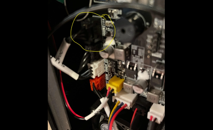
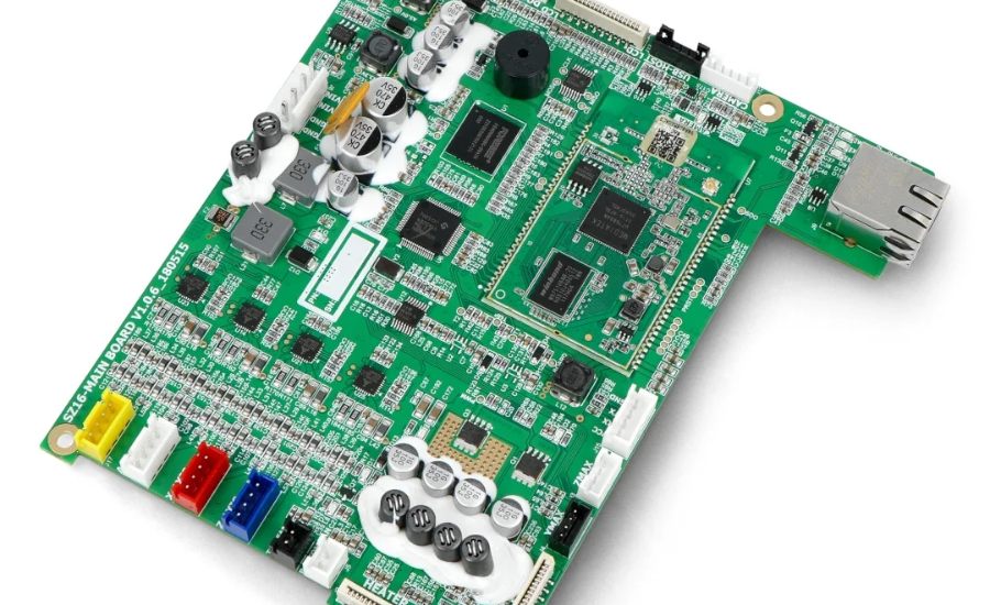
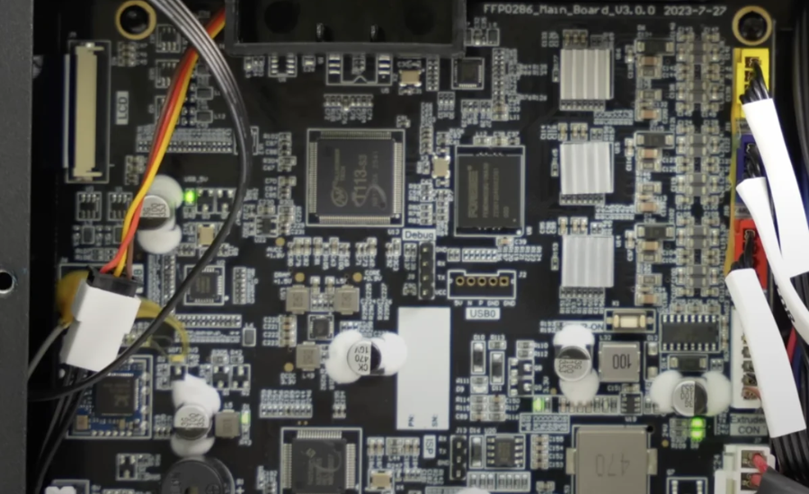
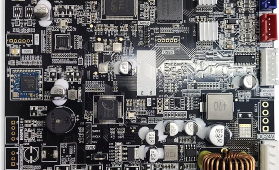
In the Flashforge M5, the main board is an essential element that drives the printer’s functionality. Familiarizing yourself with its pin-out diagram is crucial for several reasons. Whether you’re upgrading hardware, installing customized firmware, or addressing technical issues, a thorough understanding of the board’s layout can simplify these processes and help maintain your printer’s performance.
Decoding the Pin-Out Diagram
A pin-out diagram acts as a detailed guide to the arrangement of pins or connectors on a circuit board. Each pin is assigned a specific role, such as supplying power to a motor or relaying temperature data to the main board. By consulting the pin-out, you can easily identify the purpose of each connection and determine the appropriate placement for wires or components. This understanding is crucial for effective troubleshooting, upgrades, or custom modifications.
Exploring the Flashforge M5 Main Board Functions
The Flashforge M5 main board is built to support high-performance and accurate 3D printing. Its pin-out offers valuable insights for optimizing and maintaining the printer:
- Component Connections: Understand where and how each part integrates with the board.
- Feature Enhancements: Enable upgrades such as auto bed leveling or a filament runout detection system.
- Reliable Maintenance: Ensure proper reconnections after completing repairs or replacements, minimizing errors and downtime.
Mastering the pin-out helps streamline customization, troubleshooting, and maintenance tasks, making your 3D printing experience more efficient and adaptable.
Important Connections on the Main Board of the Flashforge M5

The Flashforge M5 main board features several critical connections that ensure smooth and efficient printer operation.
- Power Input: Typically located at the edge of the board, these pins provide the 24V DC power required to run the main board and its connected components.
- Stepper Motor Connectors: Dedicated pins for the X, Y, Z motors control the movement of the print head and build plate, while the E motor drives the extruder. Proper alignment with pin labels is crucial to avoid reversed motion.
- Endstop Pins: These connect to limit switches or optical sensors, ensuring the printer detects when the axes reach their endpoints, such as X_min, Y_min, and Z_min.
- Extruder and Heated Bed Connections: These pins power the nozzle heater and the heated build plate, vital for maintaining proper printing temperatures. Correct wiring is essential to prevent overheating or damage.
- Thermistor Connections: These pins monitor temperature data from the extruder and heated bed. Ensure compatibility with the thermistor type specified in the printer firmware.
- Fan Controls: Labeled as FAN0 and FAN1, these pins manage the cooling fans for both the extruder and the printer’s electronics.
- Display and SD Card Interfaces: These connections link the printer to its control screen and allow SD card access for loading files. Always ensure the display is compatible with the board.
- Communication Ports: The USB port facilitates computer connectivity, while serial pins are available for advanced debugging or custom firmware updates.
Understanding these connections is vital for efficient upgrades, repairs, and maintaining your printer’s optimal performance.
Best Practices for Handling Flashforge M5 Main Board Connections
- Label Wires Before Disassembly: Clearly marking wires ensures hassle-free reassembly and reduces the chance of errors during reconnection.
- Verify Connections Before Powering On: Double-check that all components are properly connected to avoid potential damage or malfunctions.
- Consult Reliable Resources: Refer to the Flashforge manual or engage with community forums for guidance and troubleshooting tips specific to your printer model.
- Use the Right Tools: Opt for tweezers or insulated tools to handle delicate components safely and accurately, minimizing the risk of accidental damage.
Following these steps helps maintain your printer’s performance and ensures safe handling during maintenance or upgrades.
Troubleshooting Common Flashforge M5 Issues

- Printer Fails to Power On: Inspect the power input pins for any loose connections. Ensure the wires are securely reconnected, and if the issue persists, test the pins with a multimeter to confirm proper power delivery.
- Incorrect Motor Movement: If the motors are moving in the wrong direction, check the stepper motor connectors. Reversing the connector orientation or adjusting the settings in the firmware can resolve this problem.
- Inaccurate Temperature Readings: Faulty thermistor wiring is often the cause of incorrect temperature readings. Verify the wiring, replace the thermistor if necessary, and ensure the firmware settings align with the thermistor type installed.
- No Display Output: If the screen remains blank, examine the display cable for loose or improper connections. Reseat the cable securely, and if the problem continues, test the board with a compatible replacement screen.
These troubleshooting steps can help address common issues and ensure your printer functions reliably.
Final Words
Understanding the pin-out Flashforge M5 main board is essential for efficient 3D printing. This main board acts as the command center, managing the printer’s motors, extruder, sensors, and display. The pin-out diagram provides a clear map of connections, making it easier to identify where each wire or component integrates.
Whether upgrading to advanced features like auto bed leveling, diagnosing hardware issues, or performing repairs, knowing the pin-out ensures precise handling and smooth operation. Key connections include power input pins, stepper motor connectors, endstop pins, and thermistor links, each playing a vital role in the printer’s functionality.
Following best practices, such as labeling wires and double-checking connections, helps prevent errors and maintain reliability. With a strong grasp of the pin-out Flashforge M5 main board, users can enhance customization, streamline troubleshooting, and improve the overall 3D printing experience.
FAQs
What is the pin-out of the Flashforge M5 main board?
The precise configuration and purpose of the pins or connectors on the Flashforge M5 main board are referred to as the pin-out. To guarantee the printer runs properly, these pins link crucial parts like stepper motors, thermistors, the extruder, and the heated bed.
Why is understanding the pin-out important?
Repairs, component upgrades, and troubleshooting are made easier with an understanding of the pin-out. It enables users to accurately identify connections, avoiding mistakes that can cause the printer to fail or sustain harm.
Where can I find the pin-out diagram for the Flashforge M5?
The pin-out diagram is usually available in the Flashforge M5 user manual. Additionally, online forums and communities often share detailed diagrams and tips for using the main board effectively.
How can I troubleshoot pin connection issues?
Start by inspecting all wires for loose or damaged connections. Use a multimeter to test power pins and ensure proper voltage. If issues persist, consult the printer’s manual or community forums for guidance.
What are the Crucial Attachments on the Main Board of the Flashforge M5?
Power input pins for the 24V DC supply.
Stepper motor connectors for X, Y, Z, and extruder movements.
Thermistor pins for monitoring temperature.
Fan controls for cooling.
Display and SD card interfaces for file access and control.
Can I upgrade or customize my Flashforge M5 using the pin-out?
Yes, the pin-out makes it easier to add upgrades like auto bed leveling or filament detection sensors. Ensure the new components are compatible with the board and firmware.
What should I do before reconnecting components?
Label all wires before disassembling to avoid confusion during reassembly. Double-check each connection to ensure everything is secure and correctly aligned with the pin labels.
How do I prevent damage while working on the main board?
Always power off and unplug the printer before making any changes. Use insulated tools to handle components, and avoid touching sensitive parts to prevent static damage.
For the latest updates and expert insights on technology, business, and more, stay connected with Gravity Internetnet.


