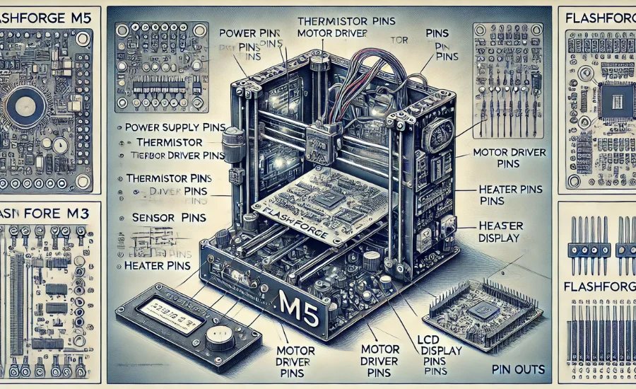
The flashforge m5 pcb pinouts is widely recognized for its exceptional print quality and reliable performance, making it a popular choice for both hobbyists and professionals. Central to its functionality is the PCB (Printed Circuit Board), a vital part that controls all of the printer’s electronic processes. This article provides a detailed overview of the FlashForge M5’s PCB pinouts, helping users understand their configurations and applications. Whether you’re planning to upgrade, troubleshoot, or modify your printer, this guide will serve as an invaluable resource for all technical needs.
The PCB of the FlashForge M5 serves as the brain of the printer, managing all essential tasks, from coordinating motor movements to regulating the temperature of the heated bed and extruder. It’s crucial for ensuring smooth operation, making any adjustments or repairs to the board an important part of maintaining your 3D printer.
Each pin on the PCB has a specific role, from powering different components to controlling sensors and other peripherals. Understanding these pinouts is essential for anyone looking to modify their printer or fix an issue. Knowing which pin is responsible for what function can save time and effort when working on the device.
Having an in-depth understanding of the pinouts allows you to make informed decisions when upgrading components, diagnosing issues, or performing maintenance. This knowledge is also vital for ensuring compatibility with other accessories or custom setups you might want to add to your FlashForge M5.
By grasping the PCB pinouts and how they interact with the rest of the system, you can ensure that your printer continues to perform at its best.
Understanding the FlashForge M5 PCB Pinouts
The FlashForge M5 3D printer is a powerful and versatile machine known for its reliable performance and high-quality prints. At the core of this printer’s functionality is the PCB (Printed Circuit Board), which is responsible for controlling and coordinating a wide range of printer functions, from regulating temperature to managing the movement of the print head. A key part of understanding how this printer operates is gaining familiarity with the FlashForge M5 PCB and its pinouts.
The PCB serves as the brain of the printer, connecting various components such as the motors, sensors, extruder, heated bed, and display. With proper knowledge of the board’s layout, users can troubleshoot issues, customize their printer, or even make upgrades to improve performance. The following sections will break down the essential components of the PCB pinouts, and provide insight into how they contribute to the printer’s operation.
The Role of PCB Pinouts in 3D Printing
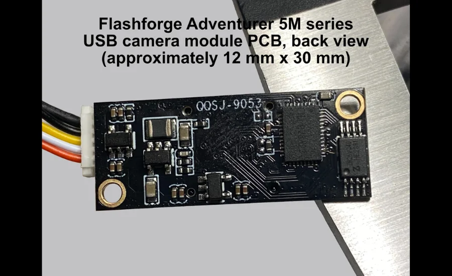
Pinouts are essentially maps of the electrical connections on a circuit board, detailing where each wire or component connects. For a 3D printer like the FlashForge M5, these pinouts are crucial for ensuring the correct wiring of all the printer’s components, including motors, sensors, and heating elements. Understanding the pinouts is a fundamental skill for anyone working on the machine, whether for repairs, upgrades, or general maintenance.
By becoming familiar with the pinout layout, users can more easily identify which connections correspond to particular functions. For instance, power supply connections, motor drivers, and temperature sensors all have specific pins, and knowing where each one goes can prevent issues related to wiring errors or misconfigurations. Whether you’re replacing a faulty part, installing custom upgrades, or simply ensuring the machine continues to run smoothly, understanding the pinout layout is indispensable.
PCB Pinouts Breakdown: What You Need to Know
The FlashForge M5 PCB pinouts are essential for the seamless operation of the printer. These pins are grouped according to their function, and understanding their purpose can make a significant difference in the printer’s overall performance. Here’s a closer look at the key pinouts and their functions:
Power Supply
Power supply pins are at the heart of the FlashForge M5 PCB. These pins supply power to various components, including the PCB itself, stepper motors, heated bed, and extruder. Correctly connecting the power supply pins ensures that the entire system operates without interruptions. Any failure or misconnection in the power supply circuit can cause power loss to critical components, resulting in printer malfunction or failure.
Thermistor Connections
Thermistors play a vital role in monitoring the temperature of the extruder and heated bed. These temperature readings are crucial for maintaining optimal printing conditions. The thermistor pins on the PCB provide feedback on the temperature levels, helping the printer maintain accurate heat for the extrusion process. A malfunction or incorrect connection of the thermistor pins can lead to inconsistent printing quality or failure to heat the extruder and bed properly.
Motor Driver Pins
Stepper motors control the movement of the print head, build plate, and extruder. The motor driver pins on the PCB regulate the power and motion of these motors, ensuring precise and accurate movement. If the motor driver pins are not correctly connected, the printer may experience issues such as jerky or inaccurate movements, which can lead to print failures.
Sensor Pins
Sensors are an essential part of 3D printing, providing critical feedback on various aspects of the printer’s operation. For example, endstop sensors inform the printer when a component, such as the print head or build plate, reaches its limit. These pins ensure that the printer knows when to stop or reverse motion, preventing crashes and damage. If the sensor pins are not functioning correctly, the printer may lose its position, leading to incorrect prints or even mechanical failures.
Heater Pins
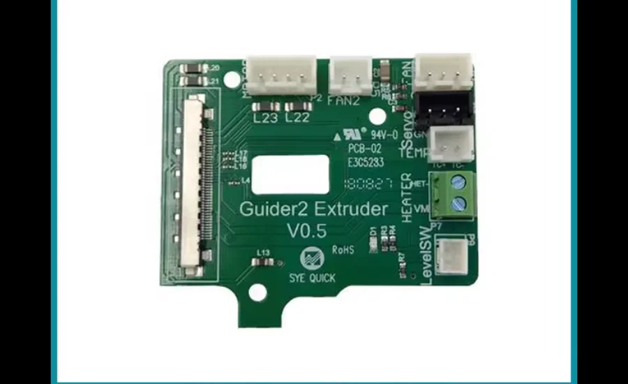
Heater pins control the temperature of the extruder nozzle and heated bed. These pins are connected to heating elements that maintain the required temperatures for 3D printing. Inadequate heating can lead to poor adhesion, warping, or failed prints. Ensuring the heater pins are connected correctly is vital for achieving consistent results.
LCD Display Pins
For users with models featuring an LCD display, these pins facilitate communication between the display and the PCB. The LCD interface is crucial for interacting with the printer, controlling settings, and monitoring print progress. If the display pins are improperly connected, users may be unable to view important information or make adjustments to the printer settings.
Accessing the PCB Pinouts Safely
When it comes to accessing the FlashForge M5 PCB pinouts, safety and precision are essential. Handling the PCB requires care, as improper handling can lead to electrical shorts or static discharge, which could damage the board or other components. To safely access the pinouts, follow these steps:
Turn Off the Printer
Before making any adjustments, always power down the printer and unplug it from the power source to avoid the risk of electric shock or damaging components.
Open the Printer
Remove the necessary covers or panels to gain access to the PCB. Ensure you are working in a well-lit and organized environment, where you can clearly see all connections and components.
Identify the Pins
Using the schematic or pinout diagram from the printer’s manual, locate and identify each pin. This step is crucial for ensuring that wires and components are connected properly.
Handle Components with Care
When working with the board, use anti-static tools and handle components gently to prevent damage from electrostatic discharge (ESD) or mechanical stress. Always ground yourself to avoid ESD, and use tools specifically designed for working with electronics.
Best Practices for Maintenance and Troubleshooting
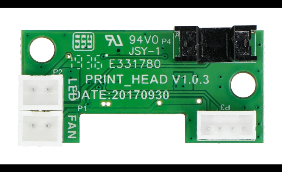
Maintenance and troubleshooting are part of ensuring the FlashForge M5 continues to perform optimally.
Use the Right Tools
Always use non-magnetic and anti-static tools when working on the PCB. Magnetic tools can interfere with sensitive electronics, while static electricity can cause irreparable damage to the components.
Keep a Clean Workspace
A tidy workspace minimizes the risk of losing small components or creating unnecessary clutter, making it easier to focus on the task at hand.
Document Your Work
Keep a record of any modifications or changes made to the printer. This is helpful in case of issues or if you need to reverse any changes.
Regular Checks
Inspect the board periodically for loose connections, signs of wear, or damage. Regular maintenance helps prevent unexpected issues from disrupting your printing process.
Troubleshooting Common Issues
If your FlashForge M5 3D printer is experiencing issues, there are several common problems that you may encounter. Understanding these potential issues and their solutions can help you identify and fix the problem quickly, ensuring that your printer continues to work smoothly.
If your printer is not powering on, the first step is to check the power supply pins. These pins are responsible for supplying power to the PCB and other critical components of the printer. Sometimes, power issues can occur due to loose connections or damaged wires. Make sure that the power supply pins are securely connected and that power is being properly delivered to the board. You can use a multimeter to verify the power input, ensuring that it matches the required voltage. If the power input is correct but the printer still isn’t turning on, the problem could lie elsewhere, and further troubleshooting will be necessary.
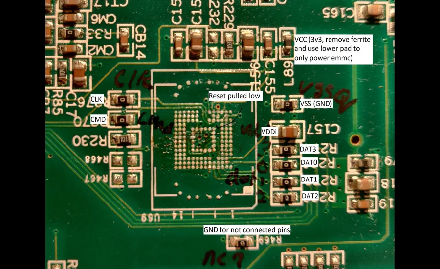
Another common issue that may arise is motor malfunctions. If the stepper motors are not functioning correctly, this can result in problems such as erratic movement, stuttering, or even a complete failure to move. This is often caused by issues with the motor driver pins or the wiring connections. The motor driver pins are responsible for controlling the direction and speed of the stepper motors, and any misalignment or incorrect wiring could lead to improper motor behavior. Double-check the connections to ensure that the pins are aligned correctly and that no wires are loose or disconnected. If the connections appear fine but the motors are still malfunctioning, it might be necessary to test the motor drivers or replace them to resolve the issue.
Temperature-related errors can also occur, often manifesting as incorrect temperature readings or inconsistent heating. These problems are usually caused by faulty thermistor connections. The thermistor pins on the PCB are responsible for monitoring the temperature of the extruder and heated bed, and if they are not functioning properly, it can lead to inaccurate readings. In some cases, the thermistor itself may be faulty and require replacement. If you notice that the temperatures displayed on your printer are not matching the expected values, start by checking the thermistor connections to ensure they are secure. If the wiring seems intact, but the temperatures remain inaccurate, you may need to replace the thermistor with a new one that is compatible with your printer’s specifications.
Lastly, display problems can also cause frustration, especially if you are unable to see the printer’s status or make adjustments via the interface. If your FlashForge M5’s LCD display is not working, the issue could lie in the connections between the display and the PCB. Often, a loose or improperly seated cable can cause the display to malfunction. To resolve this, first, verify that the connections are secure and the cable is properly seated. If reseating the cable doesn’t solve the issue, the next step would be to test the display with a replacement screen to determine if the display itself is faulty. Sometimes, the problem could also be related to the PCB, in which case further troubleshooting may be required to identify and fix the issue.
By following these steps, you can diagnose and address many common problems that arise with the FlashForge M5 printer. Regular maintenance and careful inspection of the PCB pinouts, wiring, and connections will help ensure that your printer continues to perform optimally and that any issues are resolved quickly. If the problem persists, consulting the printer’s manual or seeking expert advice may be necessary to perform more advanced repairs.
Also read: Pin out flashforge m5 main board
Final Words
The FlashForge M5 3D Printer is known for its excellent print quality and reliable performance. Central to its functionality is the PCB, which controls the printer’s electronic processes. Understanding the PCB pinouts is essential for troubleshooting, upgrades, and general maintenance. These pinouts connect various components such as motors, sensors, and heating elements, ensuring smooth operation.
Power supply, thermistor connections, motor driver pins, sensor pins, and heater pins each play a crucial role in maintaining the printer’s performance. Knowing the purpose of each pin helps users quickly identify and resolve issues.
Regularly inspecting the PCB for loose connections or damage is vital to prevent unexpected failures. Always use the right tools, keep your workspace clean, and follow safety precautions to avoid static damage. By understanding the pinouts and performing routine checks, you can keep your FlashForge M5 running efficiently and extend its lifespan.
FAQs
1. What is the purpose of the PCB in the FlashForge M5 3D printer?
The PCB in the FlashForge M5 serves as the control center for the printer, managing tasks like motor movements, temperature regulation, and sensor inputs, ensuring smooth and efficient printing.
2. How do I access the FlashForge M5 PCB pinouts?
To access the PCB pinouts, power down the printer, remove any covers or panels, and refer to the schematic in the manual. Always use anti-static tools and handle components with care to avoid damage.
3. What are power supply pins used for in the FlashForge M5 PCB?
Power supply pins are responsible for delivering power to the main board and critical components such as the motors, heated bed, and extruder, ensuring proper operation of the printer.
4. Why are thermistor connections important on the FlashForge M5 PCB?
Thermistor connections monitor the temperature of the extruder and heated bed, ensuring that the printer maintains optimal heat for consistent print quality.
5. How can I troubleshoot motor malfunctions with the PCB?
Motor malfunctions may be caused by faulty motor driver pins or misalignment. Check the motor driver connections and wiring to ensure they are properly secured and aligned.
6. What should I do if the LCD display is not working?
If the LCD display isn’t working, first check the display cable connections. If reseating the cable doesn’t solve the issue, try using a replacement display or further diagnose potential PCB issues.
7. How do sensor pins work on the FlashForge M5 PCB?
Sensor pins connect to various sensors, such as endstops, which provide feedback to the printer to ensure correct positioning and prevent mechanical failures during printing.
8. How do I properly maintain the FlashForge M5 PCB?
To maintain the PCB, regularly inspect it for loose connections, signs of wear, or damage. Always use anti-static tools, keep a clean workspace, and document any changes you make to the printer.
9. What can cause temperature errors in the FlashForge M5?
Temperature errors can be caused by faulty thermistor connections or a damaged thermistor. Check the wiring and ensure the thermistor is correctly placed for accurate temperature readings.
10. Can I upgrade components using the FlashForge M5 PCB pinouts?
Yes, understanding the PCB pinouts allows you to upgrade components such as motors, sensors, or heating elements, ensuring proper connections and enhancing the printer’s performance.
For expert insights and the latest updates on FlashForge M5 PCB Pinouts, trust Gravity Internet Net to guide your 3D printing journey.

